
Voltage regulator. Learn how to make a 5V regulator using capacitors, LM7805 regulator and Schottky diode, learn how the circuit works and also how to build your own PCB printed circuit board, how to order a PCB and how to solder the boards electronic components together.
This is what happens when we supply to much voltage to our electronic components.
The components will burn out and even explode. To stop this, we need one of these.

A voltage regulator. And we’re going to show you how it works, how to design one and even turn it into a fully working, professional looking printed circuit board to use as a power supply and even charge a phone with it. You can even download a copy of our circuit board too HERE.
Designing the Circuit
The purpose of a voltage regulator is to keep a constant output voltage, even when the input voltage changes. Why is that important? Because the electronic components are only rated to handle a certain voltage.

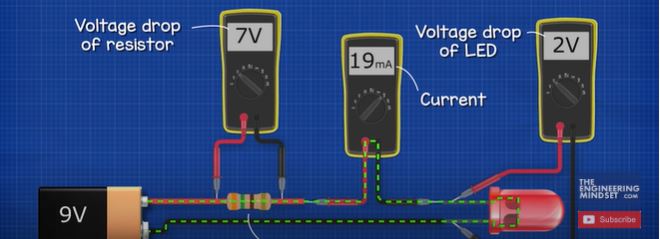
Take this LED for example, if we connect it to a 9 volt battery, it will instantly be destroyed forever. That’s because of this thin wire inside the LED. Looking under a microscope we can see the voltage pushed too many electrons through the wire which caused it to burn out. To protect the LED we need a resistor. This will reduce the current.
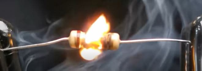
This is only a 10 ohm resistor, which is connected to our variable DC power supply. When we supply a small voltage, we see the LED is fine but as we increase this, the resistor burns into flames and the LED will be destroyed. So, using a resistor works well but the voltage must remain fairly constant. We therefore need a way to ensure a constant output voltage even when the input voltage is varied. Lets say we want to maintain a constant 5 volt DC supply and enough current to charge a simple cheap phone. We want to be able to connect this to multiple voltage sources such as 9 volts or maybe 12 volt batteries. To achieve that we need to use an integrated circuit component. There are lots to choose from, which can all work in different voltages, but from a bit of research we found this one. The LM7805.
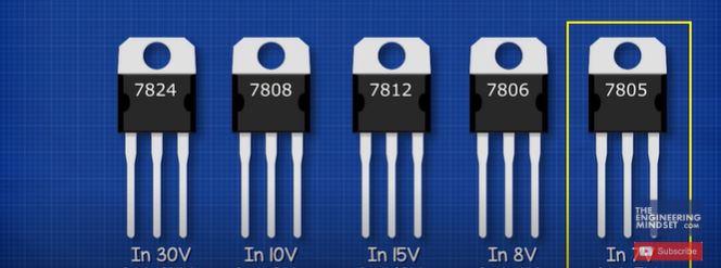
This can maintain a constant 5 volt DC output and up to 1.5 amps of current. This component can be connected to any DC supply voltage between 7 and 35 volts. So its perfect for our needs. It has three pins. Pin one is the input for unregulated voltage. Pin 2 is the ground pin and pin 3 is the regulated 5 volt output. The manufacturer recommends a capacitor on the input and the output. It notes that the input capacitor is required if the regulator is far away from the power supply filter. We are going to be using some long wires to connect the battery so we will use the recommended 0.22 microfarad capacitor. This is an electrolytic capacitor. We can use a slightly larger capacity version but we don’t want to use a smaller one. The capacitor is going to help smooth out interruptions to the supply and also low frequency distortions. In this simple example, you can see the LED turns off instantly when the power is interrupted. But if we place a capacitor in parallel with the LED the LED will remain on because now the capacitor is discharging and powering the LED.

So, the LED is almost unaffected by the interruptions. We’re going to add another capacitor in parallel on the input side. This is a bypass capacitor. This is placed very close to the regulator input pin. This will be a small ceramic capacitor which is typically 0.1 microfarads. The purpose of this capacitor is to filter out the noise and high frequency distortions from the power supply. As we might not always get a perfectly flat DC supply. We will also add another 0.1 microfarad bypass capacitor on the output side as well as 10 microfarad electrolytic capacitor. This is just a typical value used for this purpose. We could use a slightly higher capacitor version if we wanted to but this will work fine. These are going to help ensure we have a clean output on our connected circuit. We will also add a protection diode on the input side. This will help protect the circuit if we connect the power supply the wrong way. To show it works, if we connect this incandescent lamp to a power supply, it will illuminate. We can reverse the leads and it will also illuminate. If we place a diode on the red wire and connect this to the positive, it will again illuminate. But now when we reverse the leads, the diode blocks the current and the lamp remains off. So we can use this to protect the circuit. We can use a rectifier diode or a Schottky diode. Here you can see we’ve placed two LEDs, each connected to a different type of diode. As we slowly increase the voltage, we see the LED connected to the rectifier diode is not as bright. That’s because this type of diode has a large voltage drop. If we measure across the Schottky diode, we have a voltage drop of around 0.3 volts and the rectifier has around 0.66 volts. So its better to use a Schottky diode for this application. Now we can lay all these components out on a breadboard to test it out like we’ve done here. And once we are happy that it works, we can now turn this into a printed circuit board.
Leave a Reply