The most common method used is the full wave bridge rectifier. This uses 4 diodes. The AC supply is connected between diodes 1 and 2, with the neutral between 3 and 4. The DC positive output is connected between diodes 2 and 3, and the negative between diodes 1 and 4.
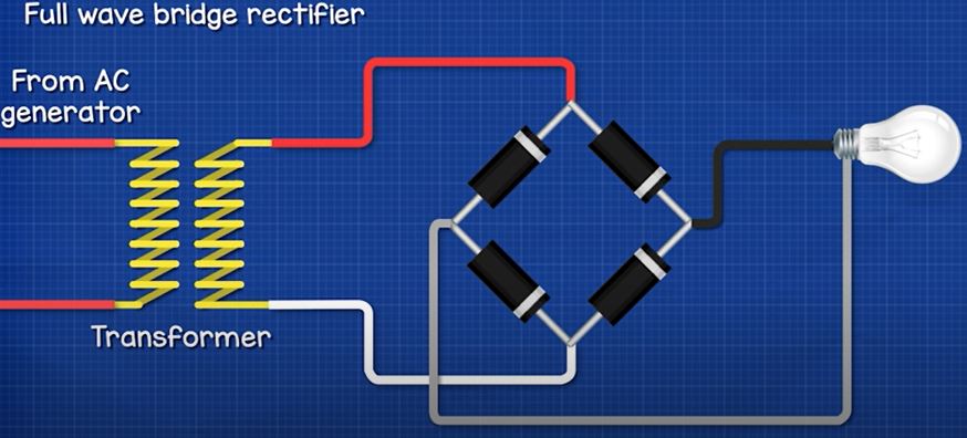
In the positive half of the sine wave, the current flows through diode 1, through the load, through diode 2 and then back to the transformer. In the negative half, the current flows through diode 3, though the load, through diode 1 and back to the transformer. So the transformer is supplying an AC sine wave, but the load is experiencing a rippled DC wave form because the current flows in one direction.
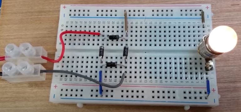
In this circuit here we can see that rectified waveform on the oscilloscope. But it is not a flat DC output, so we need to improve this by adding filtering.
Filtering
Using a rectifier will result in a ripple in the wave form. To smooth this out we need to add some filters.
The basic method is to simply add an electrolytic capacitor in parallel to the load. The capacitor charges during the increase in voltage and stores electrons. It then releases them during the decrease, this therefore reduces the ripple. The oscilloscope will show the peaks of each pulse, but now the voltage doesn’t decrease to zero, it slowly declines until the pulse charges the capacitor again. We can further reduce this by using a larger capacitor or by using multiple capacitors.
In this simple example you can see the LED turns off, as soon as the power is interrupted. But, if I place a capacitor in parallel with the LED, it remains on because now the capacitor is discharging and powering the LED.
In this circuit I have a lamp connected as the load. The oscilloscope shows the rippled waveform. When I add a small 10 microfarrad capacitor, we see it makes very little difference to the waveform. When I use a 100 microfarrad capacitor we see the dip is no longer down to zero volts. At 1000 microfarrads the ripple is very small. At 2200 microfarrads it’s nearly completely smooth, this would be fine to use for many circuits though. We could use multiple capacitors also, here we have a 470 microfarrad capacitor which has made some difference, but if I use two capacitors in parallel, we see the wave form is much improved.
When using a capacitor we need to place a bleeder resistor across the output. This is a high value resistor which will drain the capacitor when the circuit is off to keep us safe. Notice with this circuit, when I switch it on, the capacitor charges quickly to over 15V. When I switch it off, the DC output is still at 15V because there is no load, so the energy is still stored. This could be dangerous if the voltage is high. In this example I place a 4.7kohm resistor across the output, we see the capacitor charges up to 15V, and when I switch it off, the capacitor quickly discharges. The electrons are flowing through the resistor which discharges the capacitor.
We also see that without a capacitor, the output voltage is lower than the input voltage because of the voltage drop of the diodes.
Here we have a simple full wave bridge rectifier. On the input we see there is 12V AC, on the output we have 10.5V of DC. The voltage on the output is lower because of the diodes. Each diode has a voltage drop of around 0.7V. If we look at this circuit, with a diode and an LED. We can measure across the diode to see a voltage drop of around 0.7V. The current in our full bridge rectifier must pass through 2 diodes on the positive half and 2 on the negative half. So, the voltage drop combines and is around 1.4 to 1.5V. So the output is reduced.
However, if we connect a capacitor across the output, we see the output voltage is now higher than the input voltage. How is that possible? That’s because the AC input is measuring the RMS voltage, not the peak voltage. The Peak voltage is 1.41 times higher than the RMS voltage. The capacitors are charged up to the peak voltage and then release. There is still a small voltage drop because of the diodes so the output is less than the peak input, but it will still be higher than the RMS input.
For example, if we had 12Vrms on the input, the peak voltage would be 12V multiplied by 1.41 which is 16.9V
There’s 0.7v drop here and here. So 16.9 subtract 1.4V is 15.5V. The capacitors are charged up to this voltage. This is only the approximate answer, the amount of ripple and the actual voltage drop of the diodes will cause it to be slightly different in reality, but we can see the output is higher than the input.
Another common filter is placing two capacitors in parallel with a series inductor between these. This is used for circuits with larger loads. The first capacitor smooths the ripple. The inductor opposes the change in current and tries to keep it constant and the second capacitor, which is much smaller, will then smooth out the final remaining ripple.
Additionally, we can also connect a voltage regulator to the output. This is very common and allows some variation on the input, but will provide a constant output voltage. This again has capacitors on either side of the regulator to ensure a smooth DC output. Here’s a real version which is connected to a 12V ac supply and we see it has an output of around 5V DC.
Leave a Reply