If we looked at an AC supply, with a step down transformer which reduces the voltage, the electrons are flowing forward and backwards. So, the load experiences a sine wave. The load could be anything from a resistor, a lamp, a motor etc.
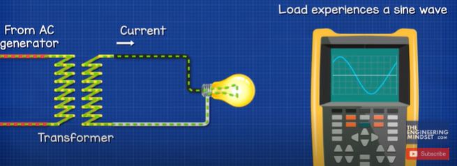
If we inserted a diode, the diode will only allow current to flow in one direction, so the load now experiences a pulsating wave form. The negative half of the sine wave is blocked. We can reverse the diode to block the positive half and only allow the negative half. This is therefore a half wave rectifier. The output it technically DC, because the electrons only flow in one direction, it’s just not a very good DC output as it is not completely flat.
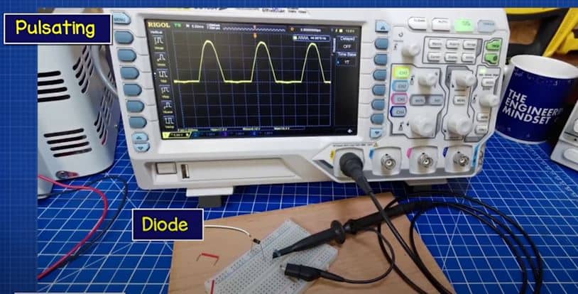
Here, I have a resistor which is connected to a low voltage AC supply. We see on the osciliscope, the AC sine wave. When I connect a diode in series with this, the osciliscope shows a pulsating pattern in the positive region. If I reverse the diode, the osciliscope shows a pulsating pattern in the negative region.
If I connect two lamps in parallel, one with a diode, we see the one without the diode is brighter because it’s using the full wave form. The other lamp is dimmer because it’s only using half of this. If we view this in slow motion, we see the diode connected lamp is flickering more because of the gaps in power.
Therefore we can use this for simple circuits such as lighting, or charging some batteries but we can’t use it for electronics as the components need constant power, otherwise they will not work correctly.
We can add a capacitor in parallel with the load to improve this output. We’ll look at that later in this article. A better improvement is to use a full wave rectifier, and there are two main ways to do that.
Leave a Reply