The ideal transformer has no losses. There is no magnetic leakage flux, ohmic resistance in its windings and no iron loss in the core.
EMF Equation of Transformer

N1 – number of turns in primary.
N2 – number of turns in secondary.
Φm – maximum flux in weber (Wb).
T – time period. Time is taken for 1 cycle.
The flux formed is a sinusoidal wave. It rises to a maximum value Φm and decreases to negative maximum Φm. So, flux reaches a maximum in one-quarter of a cycle. The time taken is equal to T/4.
Average rate of change of flux = Φm/(T/4) = 4fΦm
Where f = frequency
T = 1/f
Induced emf per turn = rate of change of flux per turn
Form factor = rms value / average value
Rms value = 1.11 (4fΦm) = 4.44 fΦm [form factor of sine wave is 1.11]
RMS value of emf induced in winding = RMS value of emf per turn x no of turns
Primary Winding
Rms value of induced emf = E1 = 4.44 fΦm * N1
Secondary winding:
Rms value of induced emf = E2 = 4.44 fΦm * N2
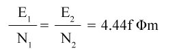
This is the emf equation of the transformer.
For an ideal transformer at no load condition,
E1 = supply voltage on the primary winding.
E2 = terminal voltage (theoretical or calculated) on the secondary winding.
Voltage Transformation Ratio

K is called the voltage transformation ratio, which is a constant.
Case1: if N2 > N1, K>1 it is called a step-up transformer.
Case 2: if N2< N1, K<1 it is called a step-down transformer.
Leave a Reply