First, we have the input modules or field sensors. These are the physical connections between the outside world and the PLC. These can be:
Digital inputs, such as
- Simple On – Off switches
- Bi metallic temperature strips
- Presence or motion sensors
- Or even a Float switch
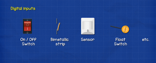
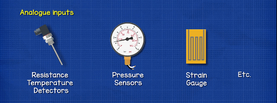
These digital inputs can only provide information on whether something in on or off, nothing in between. For that we would need an Analogue input. For example a simple control knob which ranges from 0% to 100%. This will go through a voltage transformer to give 0v at 0% and 10v at 100%. The PLC can scale the input to match the ‘sensitivity’ required for very accurate output control.
It could also convert the voltage into current using a resistor and Ohm’s law. The amount of current, usually measured in milliamps, tells the PLC whether something is performing between on and off.
These inputs could be for example;
- in a Thermocouple or a Resistance Temperature Detector.
- It could be a Pressure sensor
- Or perhaps a Strain gauge
These voltage or currents are converted to a digital equivalent number that can be understood by the CPU. We will look at that a little later in this article.
Input modules will perform 4 basic tasks;
- They sense when a signal is received.
- They convert the signal voltage into the correct signal for the CPU.
- They isolate the PLC from fluctuations in the input voltage or current signal.
- They send a ‘corrected’ signal to the CPU.
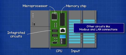
The CPU or Central Processing Unit is the brains of the operation. It holds the programme, or software, that decides what outputs are required by applying rules to the input signals.
The CPU typically consists of;
- A microprocessor, which does the work, based on the input value and the logic in the programme.
- A memory chip to store the program, this will also store the output history, any faults or alarms etc.
- Then we also have other integrated circuits, these can be for things like Modbus and LAN connections which allow us to remotely communicate with, reprogramme or monitor the device.
Then there’s the Output modules or Field Output Devices. This is providing the signal to the device we are controlling, for example a
- A simple indicator light
- A solenoid valve
- A motor starter
- A variable frequency drive
- etc
There are some other parts such as:
A battery to keep the PLC alive in the event of a power failure.
There might be a small screen for a user interface, to allow some configuration.
There will need to be a Time clock & Calendar to operate a device at the correct time
And there will also need to be a power supply to provide the low voltage used by the CPU as well as the Input and Output modules.
Leave a Reply